SMPS Power plant for Telecom Installations: Power supply system is the heart of telecom systems & electronic equipments. For a reliable installation of telecom assets, reliable power supply system is most important.
In AC electrified area, the main power is derived from the traction supply. This supply is very reliable but its occasional interruption/ low voltage can not be ruled out. In non- electrified area, the main supply is obtained from commercial power supply.
The source of power supply is through a rural feeder, which is quite unreliable in respect of its availability and voltage. The battery backup is provided in all the DC circuit, which requires more
maintenance.
The function of SMPS Power Supply system is to provide a stable and reliable AC and DC
power supply to the telecom installations against mains supply variations or interruptions.
The SMPS Power Plant for Indian Railway telecom circuits shall be manufactured as per
RDSO’s Specification NO. RDSO/SPN/TC/23/99. This Power plant can work either with
VRLA or Conventional Lead Acid Battery. The system including FR/FC or FR/BC modules
shall be suitable for operation from AC mains or from a DG set.
Important abbreviations
- A Amperes
- AH Ampere Hour
- CSU Control Supervisory Unit
- dB Decibel
- dBA Decibel Absolute
- DC Direct Current
- EMI Electro Magnetic Interference
- FR/FC Float Rectifier cum Float Charger
- FR/BC Float Rectifier cum Boost Charger
- KHz Kilo Hertz
- LED Light Emitting Diodes
- LCD Liquid Crystal Device
- LVDS Low Voltage Disconnect Switch
- MOV Metal Oxide Varistor
- MTBF Mean Time between Failures
- MMIB Mains Monitoring Interface Board
- MUIB Master User Interface Board
- ms Milli Seconds
- PCB Printed Circuit Board
- SMPS Switch Mode Power Supply
- V Volts
- VRLA Valve Regulated Lead Acid
General & Technical Requirements
SMPS is intended to be used in Auto Float Rectifier-cum Float-Charger (FR/FC) and Float
Rectifier cum Boost Charger (FR/BC) mode as a regulated DC Power Source.
Power System Configuration
The configuration of 48 V DC power plant with FR/FCs & FR/BCs modules is as under:
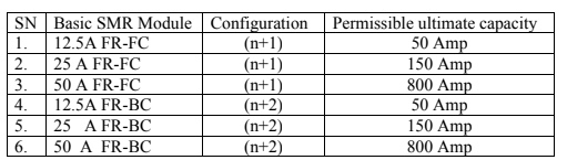
The number of FR/FC or FR/BC modules as required for meeting a particular load shall be
housed in (n+1) or (n+2) parallel configuration in a single rack where ‘n’ is the actual
required number of FR/FC, FR/BC modules.
Rack Configuration
Rack is composed of following units accommodated in sub racks
Float Rectifier cum Float Charger (FR/FC) or Float Rectifier cum Boost Charger
(FR/BC) modules.
Distribution, Switching, Control Alarm unit (arrangement) (DSCA)
Dimensions
Dimensions of the rack for all the capacities are as follows:
Height: 2200mm (max)
Depth: 600mm (max)
Width: 600mm (max)
The insulation resistance of a fully wired FR/FC when tested with a 500V DC megger shall
be as given below:
a) AC input and Earth – Greater than 2 Mega Ohm
b) DC Output and Earth – Greater than 1 Mega ohm
c) AC input and DC output – Greater than 5 Mega Ohm.
Radio Frequency Interference Suppression
The module is designed to minimize the level of electromagnetic interference (EMI), both
conducted and radiated, detected in its vicinity and generated by Switch Mode Power
conversion equipment operating within the rack.
Earthing
All non-current carrying metal parts are bonded together and earthed. An earth terminal
suitable for taking minimum 4 mm dia wire and with suitable marking is provided.
Module Replacement Time & MTBF
The mean time to replace a faulty rectifier module is less than 20 minutes. The MTBF of the
system shall not be less than 70,000 hours.
Float Rectifiers cum Charger Modules
The FR/FC modules used are accommodated in a rack in the standardized capacities of
12.5A, 25A & 50Amps.
The module is capable of operating in ‘Auto Float-cum-Charge’ mode. It is programmed
to operate as a float rectifier or a charger depending on the condition of the battery sets
being sensed by the DSCA.
The float voltage of each rectifier module is continuously adjustable & pre-settable at
any value in the range of 48V to 56V. The prescribed float voltage setting is 54 V
(VRLA battery).
The DC output voltage is maintained within 1% of the half load preset voltage in the
range 25% load to full load when measured at the output terminals over the full specified
input range.
In Auto charge mode FR/FC is supply battery & equipment current till terminal voltage
reaches set value, which is normally 2.3 Volt per cell (55.2V) & changeover to constant
voltage mode. It shall remain in this mode till a changeover to float mode signal is
received.
The float and charge current limit adjustment is provided on the front panel of the
rectifier module.
The FR/FC module is fully protected against short circuit. Ensured that short circuit does
not lead to any fire hazard.
Soft Start Feature
Slow start circuitry shall be employed such that FR/FC module input current and output
voltage shall reach their nominal value within 10 seconds.
The maximum instantaneous current during start up shall not exceed the peak value of
the rectifier input current at full load at the lowest input voltage.
Voltage overshoot/undershoot
The FR/FC modules shall be designed to minimize output voltage overshoot/undershoot
such that when they are switched on the DC output voltage shall be limited to 5% of
the set voltage & return to their steady state within 20ms for any load of 25% to 100%.
The DC output voltage overshoot for a step change in AC mains shall not cause shut
down of FR/FC module and the voltage overshoot shall be limited to 5% of its set
voltage and return to steady state within 20 ms.
The modules shall be designed such that a step load change of 25 to100% shall not result
in DC output voltage overshoot/undershoot of not more than 5% and return to steady
state value within 10ms without resulting the unit to trip.
Electrical Noise
The rectifier (FR/FC) modules is provided with suitable filter on the output side.
A resistor is provided to discharge the capacitors after the rectifier modules have stopped
operation and the output is isolated.
Parallel Operation
FR/FC or FR/BC modules is suitable for operating in parallel with one or more modules of
similar type, make and rating, other output conditions remaining within specified limits.
Protection
DC overvoltage protection
Each rectifier module is fitted with an internal over-voltage protection circuit.
In case output DC voltage exceeds –57V 0.25V the over voltage protection circuit shall
operate & shut off the faulty module. Restoration of the module is through a reset
switch/push button.
Shutting-off of faulty FR/FC module shall not affect the operation of other FR/FCs
operating in the rack.
Operation of over-voltage shut down is suitably indicated on the module and also
extended to monitoring/control unit.
The over voltage protection circuit failure shall not cause any safety hazard.
Alarms and Indicating Lamps
Visual indications/display such as LEDs, LCDs or a combination of both shall be provided
on each FR/FC module to indicate.
Functional Indications
A Mains available
B FR/FC on Auto Float
C FR/FC on Auto Charge
Alarm Indications
A Rectifier module overvoltage, under voltage or Output Fail
B FR/FC or FR/BC Over Load
C Fan fails (due to any reason)
Termination
The AC input connection to the rectifier module is by means of screw-locking type
pluggable/Rail mounted screw connectors.
The DC output connection for smaller rating (up to 25 Amps) is taken through screw
type pluggable connectors with complete non-ferrous metal parts. For higher rating
suitable termination lugs shall be provided.
The output of each rectifier in the negative lead is taken through the full rated fuse/MCB
in the distribution, switching, control alarm arrangement or in the FR/FC (FR/BC)
module.
The male connectors is preferably be mounted in the FR/FC or FR/BC module and
female connectors be terminated to the cable.
Distribution, Switching Control and Alarm Unit (DSCA)
)
Depending on the system requirements and manufacturer’s design, one or all power plant
racks are provided with a distribution/switching/control and Alarm unit (arrangement) for
the ultimate system capacity.
The unit shall comprise of the following:
Termination for the batteries
Termination for the load
Interconnecting arrangement for power equipment
Battery Switching Arrangement (Connection to/isolation from system)
Termination for AC input to the rack
Termination for AC and DC to FR/FC modules
Circuit Breakers/fuses etc.
Dimensions
The distribution/switching sub-system of the equipment shall preferably be in the modular
form whereas control, alarm &monitoring sub-system shall only be modular. The
distribution/switching sub-system may be accommodated in a rack with other FR/FCs or in a
separate rack. These sub-systems shall be rack mountable.
The unit preferably be housed in the upper portion of the rack above the FR/FC or FR/BC
modules and equipped to meet the ultimate system capacity.
Accessibility
All the termination points shall be easily accessible from front, rear or top.
AC and DC termination are modular in design with all non-ferrous metal parts.
The AC modular earth terminal is touch proof with universal yellow green housing
symbolizing the potential earth with all non ferrous metal parts including the screws.
AC Termination
The input terminals are marked as R, Y,B and N for three phase and L and N for single
phase as applicable.
AC input termination is suitably protected against the accidental touch/contact with the
working staff for their protection and shall also have clear and prominent “DANGER”
Marking.
Screening is provided between AC & DC components to prevent accident.
All the connections between distribution and FR/FC or FR/BC are through proper rated
cables only.
Fuses and circuit breakers for each FR/FC or FR/BC are easily accessible and properly
rated.
Proper terminations for AC at the input of the circuit breakers and its output to the
FR/FC, FR/BC
DC Terminations
Connection between FR/FC, FR/BC and DC distribution is through a proper rated
lugged cable/buster. Wherever cables are used, the same is terminated through the
appropriately rail mounted screw locking type terminal blocks with all non-ferrous metal
parts.
The DC output to battery and load is through cable.
The provision for interconnection between load & FR/FC, FR/BC or battery (along with
switching arrangement) & terminations for load, battery & FR / FCs. FR / BC is
provided. The isolation of any of the battery from the load shall create an alarm.
The proper rated fuses/circuit breakers are provided on the –ve DC lead from the FR /
FCs, FR / BC ( if not provided at FR/FC, FR/BC module).
All the AC, DC and control/alarm cabling are supplied with the rack.
All DC + ve and –ve loads are clearly marked.
All conductors are properly rated to prevent excessive heating.
Alarms
Following visual indications/display such as LEDs, LCDs or a combination of both shall be
provided to indicate.
i Functional Indications कायामत्मक संके त
Mains Available ( not mandatory if provided at module level)
FR/FCs, FR/BC in Float
FR/FCs, FR/BC in charge mode
Alarm Indications
Load voltage high (above 57V)/Low (below 44.4V)
FR/FC, FR/BC fail
Mains out of range
System over load
Mains ‘ON’/Battery discharge
Fan fail (in case fan provided at rack level)
Temp. Compensation fail
Battery fail/isolated
All alarm circuits are provided with suitable delay to ensure that they do not operate to
transients.
All the protections/alarms are within tolerance of 0.25V in case of DC voltage, 1% in
case of current and 5V for AC voltage.
Every alarm condition is accompanied with an audio alarm with audio cut-off facility.
Two nos. of Potential Free Contacts (one for alarm and one redundant) is provided for
extension of alarms to Centralized Display.
As an optional requirement, two numbers of potential free contacts for connecting to
network monitoring system for monitoring DC output fail, DC output over voltage, DC
output under voltage and mains fail is provided.
Latest Posts
- SMPS Power plant for Telecom InstallationsSMPS Power plant for Telecom Installations: Power supply system is the heart of telecom systems & electronic equipments. For a reliable installation of telecom assets, reliable power supply system is …
- Commands for troubleshooting SFP optical levels OTDR testCommands for troubleshooting SFP optical levels OTDR test:To troubleshoot a link flapping port that has been err-disabled, use these diagnostic tools to isolate whether the fault lies in the fiber optics or …
Read moreCommands for troubleshooting SFP optical levels OTDR test
- [Solved]link flap cisco switch port error disabledlink flap cisco switch port error disabled: A Cisco switch port enters err-disabled state due to link flapping when the interface toggles up/down rapidly (typically 3+ times within 10 seconds), …
- [Solved]Sibling Issue in Cisco SwitchSibling Issue in Cisco Switch: Based on Cisco documentation, the error message %SYS-4-CHUNKSIBLINGSEXCEED: Number of siblings in a chunk has gone above the threshold refers to a scenario where a …
- Native VLAN Mismatch Smart port enabled in Cisco switches CBS 350Native VLAN Mismatch Smart port enabled in Cisco switches CBS 350: Smartport is a Cisco feature that automatically applies a set of preconfigured commands (called macros) to a switch port …
Read moreNative VLAN Mismatch Smart port enabled in Cisco switches CBS 350
- [100% Working]password complexity disable cisco CBS 350password complexity disable cisco CBS 350: In newer firmware for the Cisco CBS350 (specifically version 3.2.0.84 and later), Cisco introduced “Mandatory Password Rules” that cannot be disabled via the Web …
Read more[100% Working]password complexity disable cisco CBS 350
- [Solved!]VPN not working on mobile dataVPN not working on mobile data: If your VPN works on Wi-Fi but fails on mobile data, it is usually due to carrier protocol restrictions or a mismatch between the …
- [100% working]How to restore deleted files from PC or PendriveRestore deleted files: The deleted data can be recovered by using a command winfr (Windows File Recovery). How to restore deleted files from PC Firstly, open Command Prompt as an …
Read more[100% working]How to restore deleted files from PC or Pendrive
- Cyber Security Tools for Security ProfessionalsCYBERSECURITY TOOLS FOR SECURITY PROFESSIONALS: Cybersecurity professionals rely on specialized tools to safeguard digital infrastructures, identify vulnerabilities, and mitigate risks. These tools enable proactive defense mechanisms, ensuring the security of …
- .MSI and .EXE Files Difference|Comaprison of MSI and EXE Files
 .MSI and .EXE Files Difference: To install a Windows program, we often have to deal with MSI and EXE files. However, there’s a difference between them. The difference between a …
Read more.MSI and .EXE Files Difference|Comaprison of MSI and EXE Files